This guide will walk you through on how your VBS(Video Base Station) operates and quick troubleshooting steps.
Design
You will notice the all-in-one VBS is much larger, has acrylic on the sides and a silver bracket on top for wires to feed into the case. The all-in-one vbs also has a swinging door to access the inside of the vbs.
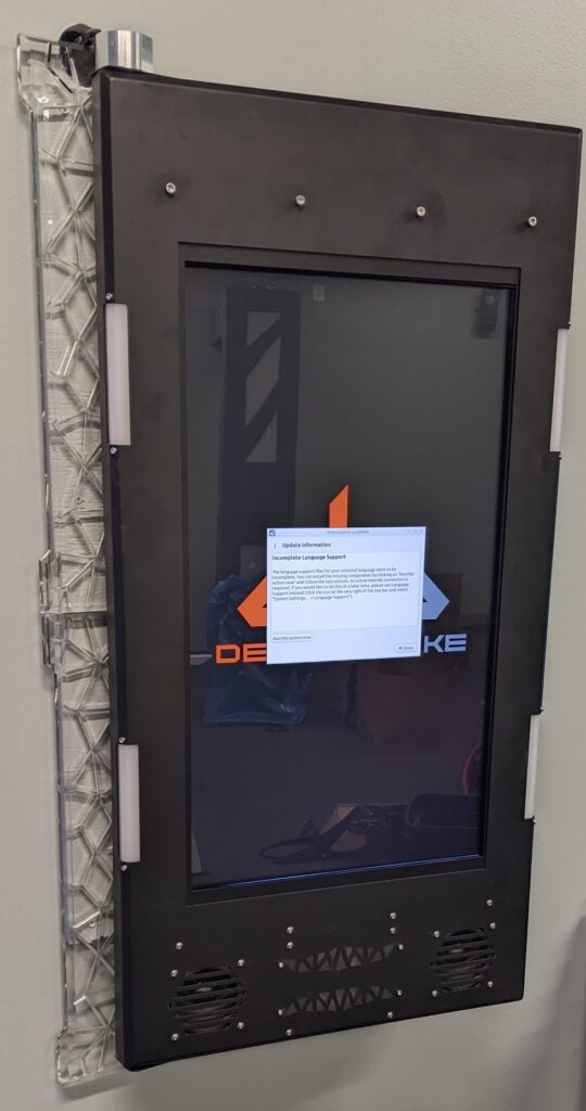

Powering on the VBS
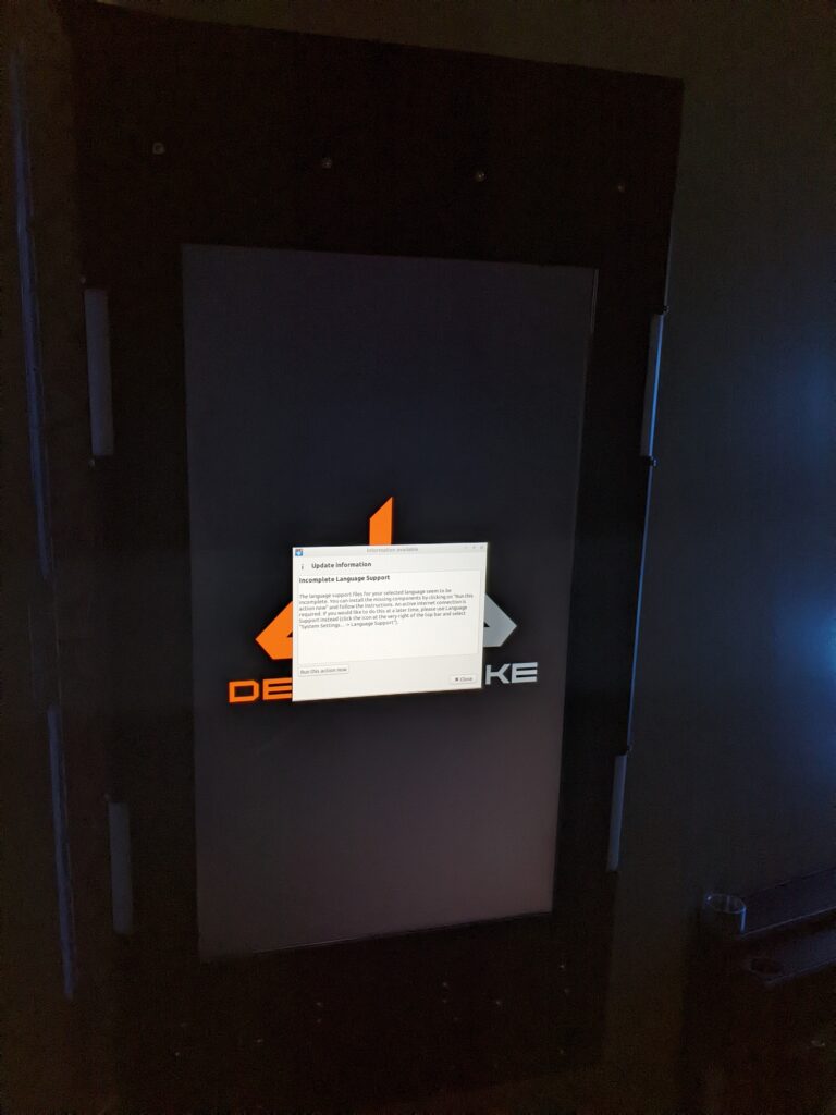
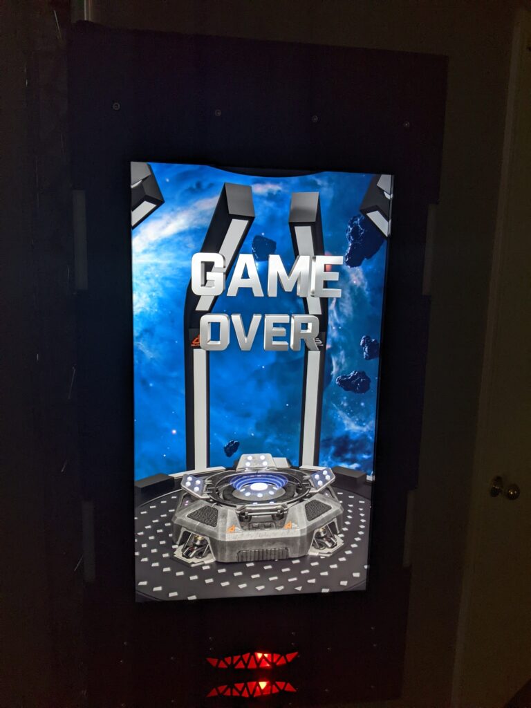
When your vbs powers on for the first time the LEDs around the VBS will light up and it will display one of two options. The first one being a DS logo saying Delta Strike and the other saying Game Over. Once connected to the server the 5 LEDs on the VBS will turn off.
How to verify the VBS is connected
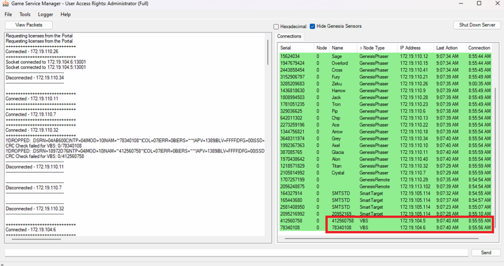
To verify the VBS is working we always recommend checking the game server. On the game server you will look for the Node Type. You can see in this photo that the Node Type says VBS and it is green, meaning the Game Server is talking to the VBS. If the VBS is connected to the server, but showing the DS logo, restart the game server. This will send a packet to update the VBS to show Game Over.
When is a VBS not going to work
There are a couple of ways to know if a VBS is not working. Here is a list of those faults.
- The entire VBS will not power on.
- The monitor does not power on.
- The VBS powers on, but the display does not show DS or Game Over.
- The VBS powers on, but shows ‘no signal’.
- The VBS powers on, but the lights around the VBS keep flashing.
How to powercycle a VBS
There are a few ways to power-cycle a VBS. First method is if you have a light switch that controls the arena components switch them off and back on. If you want to power off and on one VBS you can find the outlet controlling it and remove power from it. Another option is to open the VBS, remove the power cable and plug it back in. This will require an 8mm allen key to remove the bolts on the right hand side.
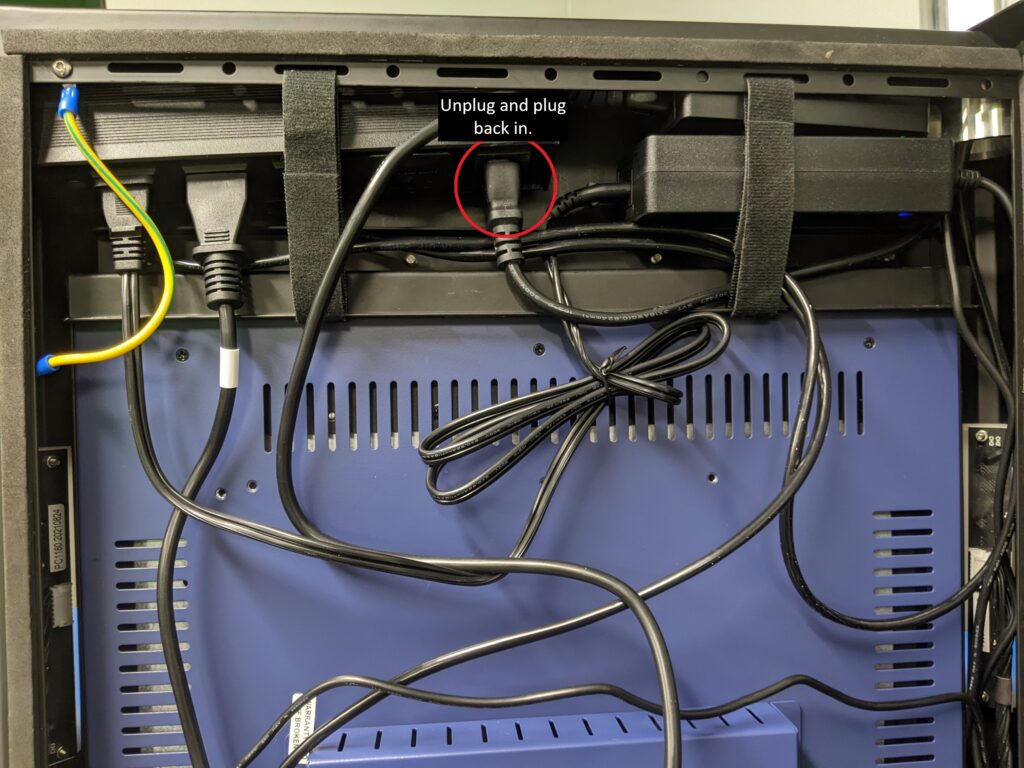
Checking connections to VBS
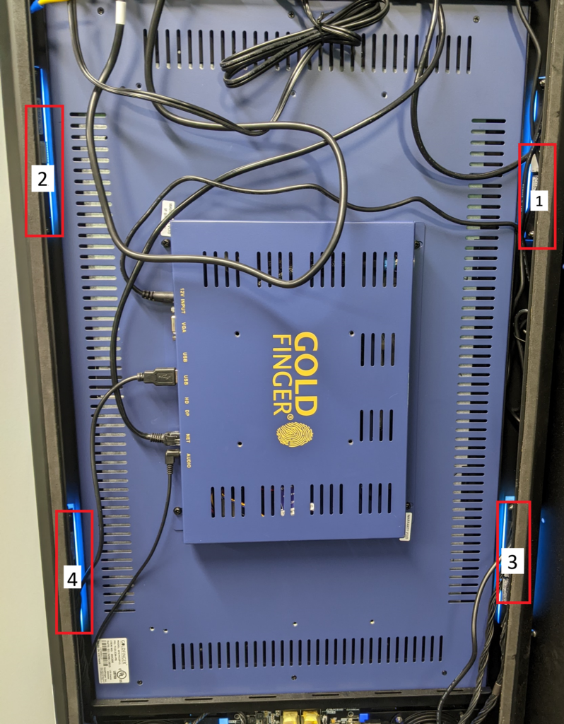
In order for the all-in-one to function, all connections will need to be installed correctly.
- 12v input is the power for the monitor. This has a specific power brick from Goldfinger.
- USB cable connects from the monitor to the VBS mainboard to allow communication. Any USB port can be used.
- Net is the ethernet line that runs to the laser tag network switch. If you have two ethernet ports this must be plugged into the bottom port.
- Audio runs from the monitor to the VBS mainboard to allow audio to play from the speakers.
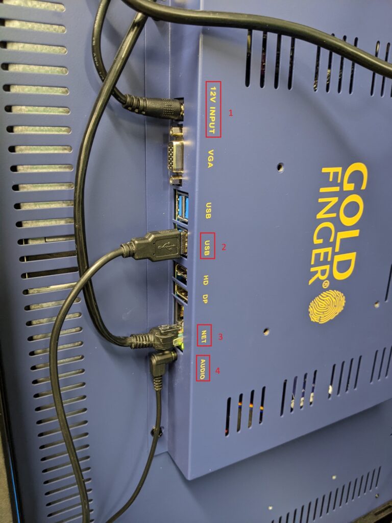
Connections to the VBS mainboard
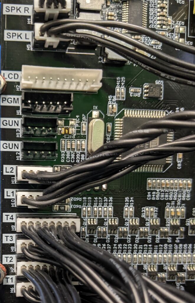
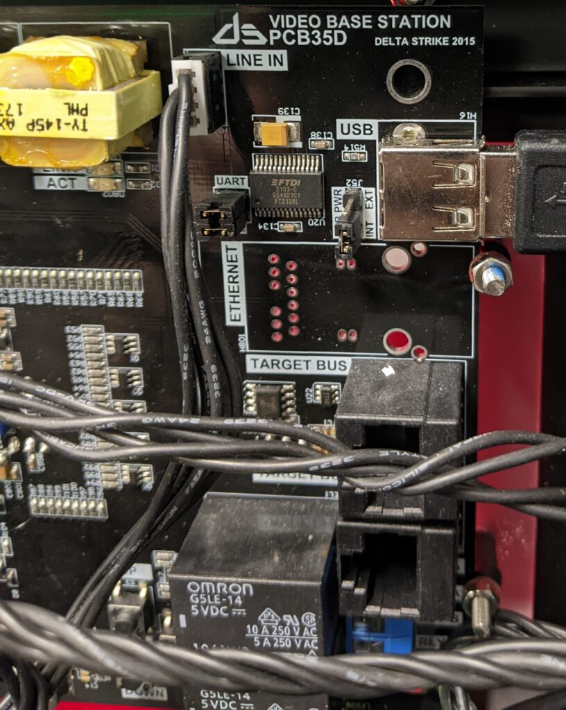
All connections on the mainboard are labeled for you as follows in the photo below. All other connection points will not be used.
- Speaker R(right) and L(left) go to the speakers at the bottom of the VBS.
- L1 and L2 are the LED light strips inside of the VBS frame that shine onto the acrylic wings.
- T1, T2, T3, and T4 are the four LED targets around the frame of the VBS.
- This is your 24v power supply.
- Line in is your audio line running to the Goldfinger monitor to allow audio.
- USB allows communication from the VBS board to the monitor.
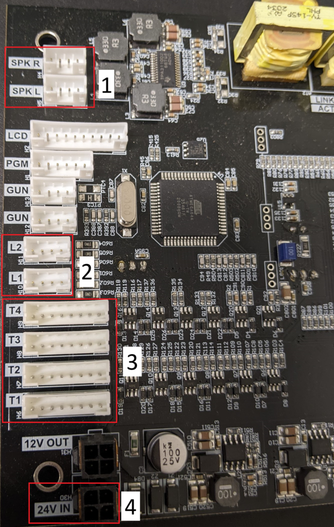
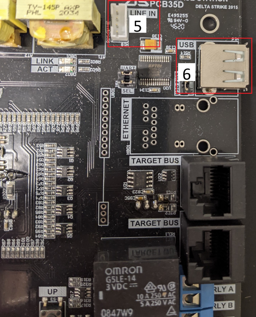
Completed setup for the VBS mainboard

When connecting T1-T4 make sure the lines are connected in the order shown in the photo.
- T1 – top right
- T2 – top left
- T3 – bottom right
- T4 – bottom left
If you have any further questions please call 888-538-2519 Ext1 or submit a ticket on portal.deltastrike.com under Support.

 Game Reports
 Equipment Diagnostics
 Order Parts
 Support
 Users
Users
